LED lighting is widely used because of its effectiveness, durability, and long lifespan. One of the trickiest things about utilizing LEDs is controlling their brightness. Here, PWM dimming is relevant. control of LEDs PWM dimming is a method for regulating LED brightness by altering the pulse width of the electrical current. PWM dimming is becoming more and more well-liked as a practical and effective method of controlling LED lights.
What is PWM dimming?
PWM’s ability to control a variety of devices in each field of electronics is largely responsible for its widespread use in the modern electronics industry. PWM signals are used to dim LEDs, control motors, and run an assortment of different electrical equipment. Hence, what is the functionality of the PWM methodology?
PWM is a method for reducing the average deliverable power of an electrical signal. In addition, the procedure is completed by successfully separating the signal into its constituent parts. In terms of functionality, the switch between the load and the source may be swiftly turned on and off to regulate the average current and voltage supplied to the load.
By varying the amount of time the signal is high (ON) or low (OFF), PWM allows for a wide range of brightness (OFF). In contrast to analog dimming, which dims LEDs by altering output power, the PWM signal may either be ON or OFF at any one time, meaning that the LEDs will either get the full voltage or no electricity (i.e., providing 10V instead of 12V to alter brightness).
What is Constant Current Reduction (CCR)?
The continuous current reduction technique provides a steady current flow to the LED (CCR). In contrast to the PWM method, in which the LED state fluctuates between on and off, the LED is constantly on. Yet, you may control the LED’s brightness by adjusting or changing the current levels using CCR.
Advantages of the CCR Dimming Method:
- Ideal for remote applications that require long wire lengths and stringent EMI specifications.
- CCR drivers have higher output voltage restrictions (60 V) than PWM drivers (24.8 V). These specifications apply to Class 2 drivers that are UL-certified for use in both moist and dry environments.
Disadvantages of the CCR Dimming Method:
- LEDs’ inconsistent light generation at very low currents renders the CCR method inappropriate for applications requiring dimming below 10% of maximum brightness. In conclusion, the LED performance produced by this method at these present levels is subpar.
- Low driving current leads to an inconsistent hue.
PWM as A Dimming Signal
Let’s expand on our current understanding of pulse width modulation. Now, the PWM must be recognized as a signal.
Pulse width modulation signals consist of sequences of square-wave-shaped pulses (PWM). There are peaks and valleys in the waveform of every signal. The on-time is when the signal strength is high, whereas the off-time is when the signal strength is low.
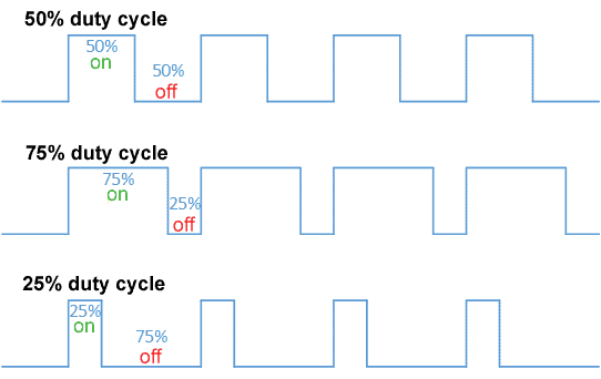
Duty Cycle
The duty cycle is when the signal can remain high in the dimming concept. Hence, the signal has a 100% duty cycle if it is always on. The PWM signal’s on-time can be adjusted. When the PWM duty cycle is set to 50%, the signal runs 50% of the time on and 50% off.
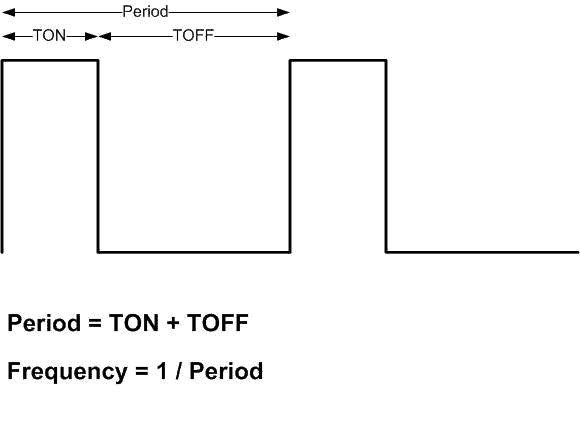
Frequency
The pulse width modulation (PWM) signal frequency is another essential component. The PWM frequency determines how quickly a period—the amount of time it takes for the signal to turn on and off—is completed by the PWM signal.
PWM as LED Driver Output
When the PWM signal is converted to a DC voltage and used as an LED driver output, pulse width modulation occurs. The PWM output circuit cuts the DC LED currents between the on and off states at a high frequency. Hence, the flicker that causes a shift in the LED light output is invisible to the human eye.
People frequently confuse a few things regarding the distinctions between PWM output and dimming signal. So let’s take note of a few things.
The mechanism produces a PWM signal as a digital signal, which makes it consistent on the dimmable cable. In contrast, the driver determines the output current by detecting the PWM duty cycle.
PWM Dimming Drivers in the Market
PWM dimming drivers are becoming increasingly crucial for LED lighting. Nonetheless, it is necessary to know that PWM dimming drivers might be realized in two different ways, and let’s find out what they are.
Fake PWM Dimming
The purpose of the fake dimming method is to convert PWM inputs into an analog control signal. A resistor-capacitor (RC) filter resides within the driver.
The RC filter converts the PWM signal to a proportional DC voltage based on the duty cycle. Fake PWM dimming has the advantage of being noiseless, and there is no noise at the output because the LED current is continuous.
Nevertheless, this method is problematic since the precision is poor if the PWM’s peak value is below 10V. Moreover, the resistor-capacitor (RC) value limits the frequency of the PWM signal.
Real PWM Dimming
In real PWM dimming, LED currents switch on and off at the frequency and duty cycle specified. The presence of the MCU or microcontroller in the driver enables the PWM signal to detect peak voltages. Real PWM dimming supports a broader spectrum of PWM frequencies.
A fundamental feature of PWM dimming is its ability to maintain the white point of the LED output. In addition, an elevated reference voltage level exceeding offset errors is permitted.
The driver development software requires users to pick PWM dimming mode.
Altering the Duty Cycle (brightness) With PWM
While the supply is switched ON and OFF so rapidly utilizing pulse width modulation output, the LEDs do not flicker. Duty Cycle is the term used to describe the measurement of PWM brightness.
The duty cycle is the proportion of the circuit’s runtime that it is ON. The duty cycle is expressed as a percentage, with 100 percent representing the brightest feasible condition (fully ON) and lower percentages resulting in poor LED light output.
The PWM signal has a 50% duty cycle if it is on 50% of the time and off 50% of the time. The signal appears as a square wave, and the brightness of the lights should be about average. When the percentage is greater than 50%, the signal spends more time in the ON state than in the OFF state, and vice versa when the duty cycle is less than 50%.
Pulse Width Modulation (PWM) vs. Analog Dimming of LEDs
With the exponential growth of LED lighting on the market, there has been a natural rise in demand for highly efficient and precisely regulated LED drivers. To preserve the energy-efficient strategy and end-use flexibility of LED design, “smart” street lights, flashlights, and digital signs, among other uses, require precisely controlled currents and, in many cases, dimming functionality.
PWM Dimming
With pulse width modulation (PWM) dimming, the LED current is momentarily on and off. To prevent a flickering effect, the on/off frequency must be quicker than what the human eye can perceive (usually over 100Hz). PWM dimming can be implemented via a variety of methods:
- Using a PWM signal to change voltage directly.
- By way of an open collector transistor
- By a microcontroller.
The average current of an LED is equal to the sum of its total nominal current and its dimming duty cycle. The designer must also take into account the delays in converter output shutdown and startup, which impose limitations on the PWM dimming frequency and duty cycle range.
Analog Dimming
Adjusting the LED current level is referred to as analog dimming. Using an external DC control voltage or resistive dimming can accomplish this. Despite the fact that analog dimming now allows for level adjustment, the color temperature can shift. Analog dimming is not recommended for applications where the hue of the LED is essential.
Let’s take a look at the primary differences between PWM & analog dimming
| PWM Dimming | Analog Dimming |
| Brightness is adjusted by modulating the peak current in the driver | Brightness adjusted by changing the DC going to the LED |
| No Color Shift | Possible Color Shift as LED current changes |
| Possible current inrush problems | No inrush current to device |
| Frequency limitations & possible frequency concerns | No frequency concerns |
| Very linear change in brightness | Brightness linearity not as good |
| Lower Optical to electrical efficiency | Higher optical to electrical efficiency(>lumens per watt consumed) |
Hardware Considerations For PWM
PWM dimming requires certain considerations when developing the system (or PC board).
A driver is typically necessary with backlight-type LEDs due to the current level. A digital output, like one from a microcontroller, cannot be used to drive it directly.
A straightforward logic level FET (Field-Effect Transistor) type transistor is typically utilized as a driver in various applications. A resistor on the gate must be used to switch the FET to control the gate current, and a resistor is necessary if the current restriction is desired. Make sure you look up the proper backlight driving voltages and currents on the LCD datasheet.
A switching-type LED driver may drive the LED backlight at higher currents and more efficiently. These drivers are more complicated, and a specialist IC often handles the switching function. The PWM input on several ICs is designed expressly for dimming applications.
If a microcontroller is being used, care should be taken to connect to an output pin that supports PWM (timer/counter) output if PWM is used as a hardware function.
PWM – Firmware/Software Considerations
PWM dimming demands particular system design considerations (or PC board).
Because to the high current, backlight-type LEDs typically require a driver. Digital outputs, such as those from microcontrollers, cannot be utilized to directly drive it.
Typically, a simple logic level FET (Field-Effect Transistor) type transistor is used as a driver in a variety of applications. Switching the FET to regulate the gate current requires a resistor on the gate, and a resistor is required if current limiting is desired. Check the LCD datasheet for the correct backlight driving voltages and currents.
A switching-type LED driver may drive the LED backlight more effectively and at greater currents. These drivers are more complex, and the switching function is frequently handled by a specialized IC. Several ICs’ PWM inputs are developed specifically for dimming applications.
If PWM is utilized as a hardware function, attention should be made to connect to an output pin that supports PWM (timer/counter) output on a microcontroller.

PWM Functionality And Applications
When the on and off periods of the switch are shifted relative to one another, the amount of electricity delivered to the load rises. As expected, this type of control offers many advantages.
PWM paired with maximum power point tracking, or MPPT, is one of the primary ways for reducing solar panel output to make it easier for a battery to use it.
PWM, on the other hand, is ideal for powering inertial equipment, such as motors, because this unique switching has less of an effect on them. Due to the linear link between LEDs’ functioning and input voltage, this also applies to LEDs.
In addition, the PWM switching frequency must have no effect on the load, and the resulting waveform must be smooth enough for the load to recognize.
Depending on the device and its function, the switching frequency of the power supply will typically vary significantly. Electric ranges, computer power supplies, and audio amplifiers all require switching speeds in the tens or hundreds of kilohertz range.
Another key advantage of adopting PWM is the incredibly low power loss in switching devices. When a switch is turned off, no current flows through it. In addition, when a switch is on and sending electricity to its load, there is a negligible voltage drop across it.
Related Articles
Everything You Need to Know About DMX512 Control
Everything you need to know About Triac Dimming for LEDs
How To Choose the Right LED Power Supply
DMX vs. DALI Lighting Control: Which One to Choose?
The Ultimate Guide To 0-10V Dimming
FAQs
Summary
PWM dimming is a simple and inexpensive method of adjusting the brightness of LED lights. PWM dimming has various advantages over analog dimming, including higher energy economy, more precise control, and longer lifespan. It does, however, present several issues, such as possible EMI and the need for high-frequency switching circuits. However, PWM dimming is an important technique for regulating LED lights, and its future seems promising.
LEDYi manufactures high-quality LED strips and LED neon flex. All of our products go through high-tech laboratories to ensure the utmost quality. Besides, we offer customizable options on our LED strips and neon flex. So, for premium LED strip and LED neon flex, contact LEDYi ASAP!