The reason flexible printed circuits were made was to get rid of the need for rigid wiring harnesses. Flexible printed circuits are used in almost every industry because of connectivity, mobility, wearables, shrinking, and other modern trends. At its most basic, a flexible circuit is made up of many conductors that are separated by a fragile dielectric film. Flexible printed circuit boards can be used for everything from the simplest to the most complicated tasks.
History Of FPCB
At the turn of the 20th century, researchers in the new telephone business saw the need for standard, flexible electric circuits. The circuits were made of alternating layers of conductors and insulators. According to a 1903 English patent, the circuits were made by putting paraffin on paper and laying out flat metal conductors. In his notes from around the same time, Thomas Edison suggested using linen paper coated with cellulose gum and drawn with graphite powder. In the late 1940s, when mass production techniques were first being used, several patents were filed for photo-etching circuits on flexible substrates. Adding active and passive components to flexible circuits led to the development of “flexible silicon technology, which describes the ability to combine semiconductors (using technologies like thin-film transistors) onto a flexible substrate. Thanks to the combination of onboard computation and sensor capacity, there have been exciting new developments in many fields with the usual benefits of flexible circuit architecture. New developments, especially in aircraft, medicine, and consumer electronics.
What Is FPCB?
As compared to the regular PCB, there are significant differences in how they are designed, made, and how they work. It’s inaccurate to say that modern manufacturing techniques are “printed .”Since photo imaging or laser imaging is used more and more to define patterns instead of printing, a layer of metal traces is glued to a dielectric material like polyimide to make a flexible printed circuit. The thickness of the dielectric layer can range from .0005 inches to.010 inches. While the thickness of the metal layer can be anywhere from .0001 inches to >.010 inches. Adhesions often attach metals to their substrates, but other methods, such as vapor deposition, are also possible. Copper can oxidize, so it is usually covered with a protective layer. Gold or solder are the most common choices because they conduct electricity and can stand up to the environment. A dielectric material is usually used to keep the circuitry from oxidizing or shorting out in places where it doesn’t touch anything.
Structure Of FPCB
Flexible PCBs can have one, two, or more circuit layers, like rigid PCBs. Most single-layer flexible printed circuits are made up of these parts:
- The dielectric substrate film serves as the PCB’s foundation. The most used material, polyamide (PI), has a strong resistance to traction and temperature.
- Copper-based electrical conductors that serve as the circuit’s traces
- A protective coating is created using a cover lay or cover coat.
- Polyethylene or epoxy resin is the adhesive substance that holds the various circuit components together.
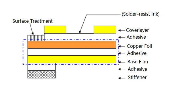
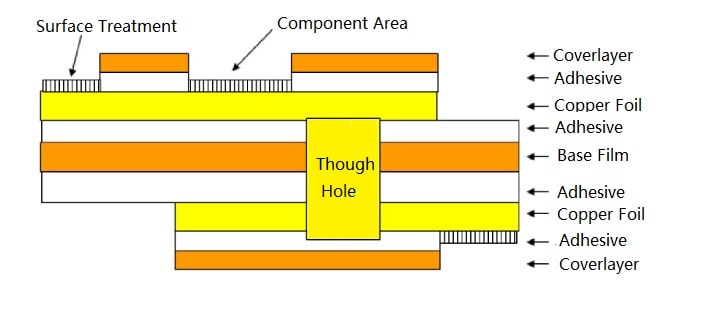
First, the copper is etched to reveal the traces, and then the protective covering (cover lay) is pierced to reveal the soldering pads. The parts are cleaned and then rolled together to make the final product. The pins and terminals outside the circuit are dipped in the tin to help with welding or keep them from rusting. If the circuit is complicated or needs copper ground shields, switching to a double-layer or multi-layer FPC is essential. Multi-layer FPCs are made in a similar way to single-layer FPCs. But, in multi-layer FPCs, a PTH (Plated Through Hole) must be added to connect the conductive layers. The adhesive material sticks the conductive tracks to the dielectric substrate or, in multi-layer flexible circuits, sticks the different layers together to make the circuit. Besides, the adhesive film can protect the flexible circuit from damage caused by moisture, dust, and other particles.
The Manufacturing Process Of FPCB
Schematic capture, printed circuit board layout, and circuit board fabrication and assembly are high-level descriptions of the steps in designing and making a PCB, but the details are complicated. In this section, we’ll look at each step.
- Construct The Schematic
Before starting to design the board with CAD tools, it’s crucial to finish designing the library components. This means making logical symbols for parts you can build, like resistors, capacitors, inductors, connections, and ICs. That you can use in the schematic (ICs). Once these parts are ready, you can start by putting them in order on schematic sheets using CAD tools. Once the pieces have been roughly put together, you can draw the wires to show how the pins of the schematic symbols connect. In electronic memory and data circuits, nets are the lines that show single nets or groups of nets. During the schematic capture, you must move the process parts around to make a clear and readable diagram.
- Circuitry Simulation
Once you draw the schematic’s parts and connections, you can test the circuit to see if it works. You can double-check this by using SPICE (Simulation Program with Integrated Circuit Emphasis) circuit simulations in a modeling program. Before making the actual hardware, PCB engineers can use these tools to simulate the circuits they have designed. PCB design tools are essential because they can save time and money.
- CAD Tool Setup
With today’s design tools, PCB designers have access to many features, such as the ability to set design rules and constraints. That keeps individual nets from crossing and gives enough space between components. Designers also have access to a wide range of extra tools. Tools like design grids. It makes it easier to place components and route traces in an organized way.
- Components For Layout
After you have made the design database and the schematic’s data on how the nets connect is imported, you can make the actual circuit board layout. First, you must put the component footprints inside the board outline in the CAD program when the designer clicks on an impression. A “ghost-line” graphic showing the net connections and which components they lead to will appear. With practice, designers will learn how to position these parts for the best performance—considering things like connectivity, hot spots, electrical noise, and physical obstacles like cables, connectors, and mounting hardware. Designers can’t think about what the circuit needs. Designers also have to think about where to put the parts so that it’s easiest for the manufacturer to put them together.
- PCB Routing
Now that everything is where it should be, you can hook up the nets. To do this, you need to make the lines and planes on a drawing from the connections in the rubber-band net. CAD programs have several helpful features, such as automatic routing functions that cut design time, which helps them do this.
It’s essential to pay close attention to routing. It is necessary to ensure that the nets’ length is suitable for the signals they’re carrying and that they don’t go through areas with a lot of noise. Because of this, cross-talk and other problems with signal integrity may affect how well the board works after it is made.
- Establish A Clear PCB Return Current Path.
You need to connect the most active parts on the board, like integrated circuits (ICs), to a power and ground net. All you have to do to make solid planes that these parts can reach is flood an area or layer. When it comes to making power and ground planes, things are more complicated. These wings also have the vital job of sending back signals along a trace. If the planes have too many holes, cutouts, or splits, the return paths can be very noisy and hurt the performance of the PCB.
- Final Check Of The Rules
Your PCB design is almost done now that you’ve finished putting in components, routing traces, and making power and ground planes. The next step is to set up the text and markings that will be silk screened onto the outside layers and run a final rules check.
Putting names, dates, and copyright information on the board will help others find parts. At the same time, you must make and use manufacturing drawings in creating and putting together PCBs. PCB designers also use tools that help them determine how much it will cost to make the board.
- Make The Board
After you create the output data files, the next step is to send them to a manufacturing facility to make the board. After you cut the traces and planes into the metal layers, You need to press them together to create a “bare board” that is ready to be put together. When the board gets to where you can put it together, You can give it the parts it needs. After that, you can put it through one of several soldering processes designed for each part. The board is finally ready now that it has passed all necessary tests.
Materials Used For Making FPCB
FPCB products are not only made of a flexible material but also feel light and thin. The structure is so light that you can stretch it many times without hurting the insulation on the PCB. The soft board can’t handle high conduction current or voltage because it is made of plastic and is made up of wires. This makes it less useful in high-power electronic circuits. But you can use soft boards a lot in low-power, low-current consumer electronics. Soft boards are rarely used as the primary carrier board in product design because their unit cost is high. This is because the key material PI controls how many soft boards cost per unit. Instead, they are hired to carry out only the “soft” parts of the critical design. Electronic components or functional modules that need to move and work need soft circuit boards. For example, the electronic zoom lens in a digital camera or the read head electronic circuit in an optical disc drive are examples of this. PI, also called Polyimide (PI), can be further broken down into fully aromatic and semi-aromatic PI. You can use it based on its molecular structure and ability to handle high temperatures. Wholly aromatic PI is a chemical compound that is one of the straight types of PI. Things can be soft or hard, or they can be both. Because they are infused, materials that can be injected can’t be shaped, but they can be crushed, sintered, and used differently. The semi-aromatic PI is a type of polyetherimide that belongs to this group. Because the material is thermoplastic, injection molding is often used to make polyetherimide. With thermosetting PI, you can use lamination molding of impregnated materials, compression molding, and transfer molding, which need different qualities in the raw materials.
Types Of FPCB
Flex circuits come in eight types, from single-layer to multi-layer to rigid. Here are some of the most common types of flexible circuits.
- Single-sided flexible circuits: These circuits have one copper layer between two layers of insulation. Or one layer of insulation (usually polyimide) and one side that isn’t covered. The circuit layout is then chemically etched into the copper layer below. Because of how they are made, components, connectors, pins, and stiffeners can be added to single-sided flexible printed circuit boards.
- Single-Sided Flex Circuits with Dual Access: Some single-sided flex PCBs have a layout that lets the circuit’s conductors be reached from both sides of the board. Using a flexible PCB and specific layers for this design function makes it possible to get to the one copper layer through the polyimide layer of the base material.
- Double-sided flex circuits: These circuits are flexible printed circuit boards with two conducting layers. These circuits are separated by polyimide insulation. The exterior sides of the conductive layer can be either exposed or covered. Most layers are connected by plating through holes, but there are other ways. Like single-sided versions, double-sided flexible PCBs can hold extra parts like pins, connections, and stiffeners.
- Multi-layered flexible PCBs. These circuits use three or more flexible conducting layers with insulating layers in between to make both single- and double-sided circuits. The outer layers of these units usually have covers and a through-hole. They are often plated in copper and run the length of the thickness of these flexible circuits. With multi-layered flexible circuits, you can avoid crossovers, cross-talk, impedance, and shielding problems. There are many ways to design multi-layered circuits. For example, blind and buried vias can build multi-layered flex boards as FR4 can. Also, you could laminate the layers of a multi-layered circuit over and over for extra protection, but this step is usually skipped if flexibility is more important.
- Rigid-flexible circuits: These PCBs are a little different than the others, and they usually cost more than other flexible PCB options, even though they serve the same purpose. Most of the time, these designs have two or more conductive layers, with either rigid or flexible insulation between each one. Unlike multi-layered circuits, they only use stiffeners to keep the unit together, and the conductors are placed on layers that are not flexible. Because of this, rigid-flex PCBs have become popular in the aerospace and defense industries.
- Aluminum flexible boards: Flexible aluminum printed circuit boards work best in industries like medicine and cars that use a lot of electricity and light. And because they are small, they may be able to go through small doorways. These are excellent investments because they are cheap, light, and long-lasting. They also have aluminum layers that help heat move through them.
- Microcircuits: Flexible microcircuit boards are the best solution for consumer electronics. Due to their lightweight and resistance to shock and vibration, these materials are perfect for consumer electronics. Microcircuits have good signal integrity, so their small size doesn’t affect how well they work.
- High-density interconnector (HDI) boards with flexible circuits: These have one of the fastest-growing technologies in the printed circuit board business. Because they have more wires than traditional circuit boards, they improve electrical performance and speed while making equipment lighter and smaller. They work great in gadgets like cell phones, computers, and video game consoles.
- Ultra-thin, flexible printed circuit boards: These have small, thin parts and board materials. This makes them perfect for electronics that need to be portable or put inside the body. Or for any other use that needs very light circuit boards.
FPCB Applications
A flex PCB is the same as a regular printed circuit board, except the circuit connections, are made with a flexible base material. This is especially helpful for things not meant to be installed permanently. Flexible PCBs are used in more and more industries because they last a long time and take up little space. The following are a few examples of where and how this technology can be used:
- Automobile industry: More and more cars have electronic parts. So, it’s essential that the circuits can handle the bumps and jolts that happen inside a car. A flexible printed circuit board is a crucial business option because it is cheap and lasts a long time.
- Consumer electronics: Flexible printed circuit boards (PCBs) are often used in consumer electronics. E.g., cell phones, tablets, cameras, and video recorders. The ability of the flexible PCB to handle shock and vibration will come in handy if you need to move these things often.
- High-speed digital, RF, and microwave applications: Flexible PCBs are excellent for high-frequency. You can use them in high-speed digital, RF, and microwave applications because they are reliable.
- Industrial electronics. Industrial electronics need flexible PCBs that can absorb shocks and stop vibrations because they have to handle a lot of stress and vibration.
- LED: LEDs are becoming the standard for lighting in homes and businesses. LED technology is a big part of this trend because it works well. Most of the time, the only problem is the heat, but a flexible printed circuit board’s good heat transfer can help.
- Medical systems: As the demand for electronic implants and portable surgical equipment rises. This makes compact and dense electronic designs more critical in the medical systems sector. You can use flexible printed circuit boards in both. Because you can bend them, and they can handle the stresses of surgical technology and implants.
- Power electronics. In the field of power electronics, a flexible printed circuit board has the added benefit of handling higher currents because it has very flexible copper layers. This is very important in the business of power electronics since devices need more power when they are running at full capacity.
The Importance Of FPCB
You can use flexible boards a lot in both dynamic and static situations because you can bend them. Compared to rigid PCBs, you can stretch circuit boards used in dynamic applications without breaking. Borehole measurements in the oil and gas industry are perfect for flexible circuit designs. Because they can withstand high temperatures (between -200° C and 400° C), even though flexible boards have their uses, you cannot use them in place of regular circuit boards. Rigid boards are a natural choice because they are inexpensive. You can use them in automated, high-volume fabrication applications. Flexible circuit boards are the way for performance, accuracy, precision, and consistent bending.
Challenges And Cost Considerations Of FPCB
When working with FPCBs, like when trying to make changes or repairs, problems can happen. You need a new base map or a rewrite of the lithography software to change the design. It’s not easy to make changes because you must first strip the board of a protective layer. Length and width are limited because of the size of the machines used to make them. Also, you can break FPCBs if you handle them carelessly. So people who know what they are doing need to solder and fix them.
Cost is always a major factor. However, the application greatly affects how cost-effective FPCBs are compared to rigid PCBs. Since each FPCB application is unique, the expenses associated with initial circuit design, layout, and photographic plates are costly for small numbers.
FPCBs may ultimately be more affordable for higher manufacturing volumes because of the fewer wires, connectors, wire harnesses, and other parts needed for assembly. This is particularly true when the upstream and downstream advantages are considered, such as the reduced supply chain risk and the decrease in maintenance requests brought on by the availability of fewer parts.
Advanced Features Of FPCB
The flex circuit industry has been growing at a steady pace. Because of this growth, there have been more improvements in technology, such as:
- Graphic Overlays: Graphic overlays allow users to talk to the circuitry underneath PCBs. They are acrylic or polyester covers for PCBs. These overlays often have LEDs, LCDs, and switches that let users talk to the PCB the way they want.
- Hot Bar Solder: You can use a hot bar solder connection instead of a connector to link a hardboard and a flex circuit. The result is a cheaper connection that is stronger and lasts longer.
- Laser Skived Slots and Holes: In the past, You could cut FPCBs with razors. And the quality of the cut depended on how good the person was at using the razor. But with the lasers we have now, we can cut lines with a lot of precision and control, which lets us make even smaller circuits on flexible PCBs.
- Panelization: Circuit boards, called PCBs, when put together in large panels of many modules. In “pick-and-place” assembly lines. This can speed up the process of putting together flex circuits by a lot. Step two is to divide the units into smaller groups.
- Pressure-Sensitive Adhesives. Pressure-sensitive adhesives stick things together by taking off a liner and pressing an object into the glue. This material is often used on printed circuit boards (PCBs) to keep circuit parts in place without using solder.
- Shielding: In the past, electromagnetic interference has been a problem. It has been a problem, especially in places where electronics are more likely to be affected by it. This is less of a problem now because shielding technology has improved. It reduced the noise and made it easier to control the impedance of signal lines.
- Stiffeners: Stiffeners made of materials like FR4 and polyimide are often added to flex circuits at connection points. The connection points where the circuit could use extra support. Because of this, the circuit will last longer and work better.
Benefits Of Using FPCB
Flex PCB technology makes it possible to make many new products and layouts. Its malleability is sought-after in electrical parts. Electrical parts like connections, wires, cables, and printed circuit boards. Here are some of the benefits of using flex circuits.
- FPCBs cut the weight of the device by about 70%.
- They give more options for better electronic packaging.
- FPCBs help you fix packing and wiring problems. This is because it is flexible, adaptable, and can change shape.
- FPCBs reduce the need for wires, connections, printed circuit boards, and cables. It helps solve the problem of how to connect things.
- The ability to produce 3D packages is made possible by the material’s conformity and slenderness.
- Electrical integration: It’s simple to create custom solutions. It allows you to base your design on many material alternatives. Also, you can select from a variety of plating techniques and styles.
- No matter how good or strong your heat sink is, a flexible printed circuit can handle the heat. So, they work well in high-power situations.
- FPCBs provide mechanical and electrical repeatability.
- They cost 30% less than traditional hard wiring and other assembly methods.
- FPCB needs about 30% less space.
- FPCB is more reliable because wiring mistakes can’t happen with it.
Drawbacks Of Using FPCB
- A flex circuit’s initial circuit design, wiring, and photographic masters are more expensive. They are expensive because you can make them for each application. Flexi-PCBs aren’t cost-effective for low-volume uses.
- The flex circuit boards are challenging to replace and repair. Once constructed, you must change flex circuits from the original design or the light drawing program. The surface has a protective layer that you’d need to remove before repair and put back on afterward.
- Because they are small, flexible printed circuit boards are rarely used. So their production is usually done in batches. Because of the size limits of the machinery used to make them, you can’t make them very long or wide.
- It’s easy to damage the flexible circuit by using it carelessly, and damage can also happen if it’s not set up right. Soldering and reworking need skilled operators because of this.
Differences Between Rigid PCBs And Flexible PCBs
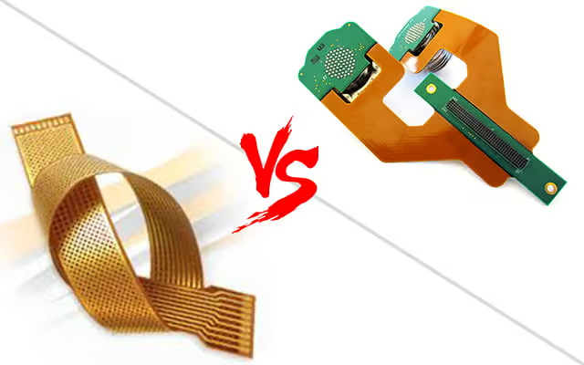
When most people think of a circuit board, they picture a hard-printed circuit board (PCB). Over a non-conductive base. These boards connect electrical parts with conductive tracks and other parts. Glass is often used as the non-conductive substrate material of a rigid circuit board. Because it makes the board strong and rigid, a rigid circuit board can keep components from getting too hot because of its robust design. You can make traditional circuit boards of hard materials like copper or aluminum. But you can make flexible PCBs that are easier to bend, such as polyimide. Flexible circuits can absorb shock, let off extra heat, and take on a wide range of shapes because you can bend them. Because they are made to be flexible, flex circuits are being used in more and more small, modern electronic devices. There are some significant differences between printed circuit boards (PCBs) and flex circuits.
- Because rolled annealed copper is more flexible than electro-deposited copper, you can use it as the conductive material in flex circuits instead of electro-deposited copper.
- In manufacturing, you can use an overlay instead of a solder mask. You can do it to protect the exposed circuitry on a flexible PCB.
- Even though flex circuits are more expensive, rigid circuit boards are less expensive. But because flex circuits are small, engineers can use them to make their devices smaller. They are saving money in ways that aren’t obvious.
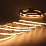
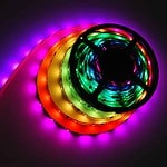
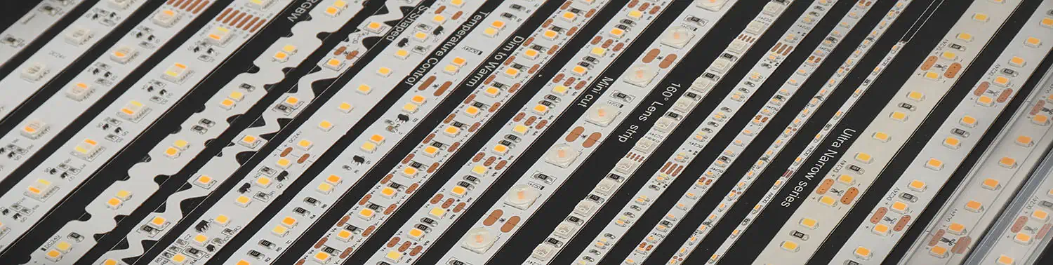
Importance Of FPCB In LED strips
As technology improves, LED strips are becoming more and more popular. LED strips are already a great way to light and decorate your home, and flexible PCB only improves things. LED strips are circuit boards that are connected to each other. SMT (Surface Mount Technology) is used to make flexible printed circuit boards (PCBs) with surface-mounted parts (SMD LEDs, connectors, etc.). . When the LED chips are being put together, the FPCB acts as a base for them. As important as the structure of a circuit board is how well it can get rid of heat. Flexible electronics are a big help when it comes to LED strip lights. Like rigid PCBs, various FPCBs are single-layer, double-layer, and multi-layer PCB circuits.
FAQs
Summary
You can bend and flex FPCs to fit various shapes and sizes. This makes them easier to design and use. You cannot put standard rigid circuits in places with odd dimensions, but flexible circuits can. Flexible circuits take up less space on the application’s motherboard. It makes them cheaper and less bulky. By making the most of all available space, better thermal management makes it so that less heat needs to be moved around. Flexible printed circuits could be more reliable and last longer than rigid PCBs, especially when the circuits are constantly shaken or under mechanical stress. FPCBs have replaced traditional connectivity methods. FPCBs have replaced them based on soldered wires and hand-wired connectors because of their cheap weight, thin profile, excellent mechanical resistance, resilience to high temperatures and atmospheric agents, and good electromagnetic immunity (EMI). Think about how hard it would be to connect all the screens, controllers, and displays in a modern car (rotary controls, buttons, etc.) because these electronics are exposed to mechanical loads and vibrations. They need a secure connection no matter how the vehicle runs. FPCBs ensure zero downtime, long service life, and minimal maintenance in the automotive industry.
LEDYi manufactures high-quality LED strips and LED neon flex. All of our products go through high-tech laboratories to ensure the utmost quality. Besides, we offer customizable options on our LED strips and neon flex. So, for premium LED strip and LED neon flex, contact LEDYi ASAP!